Quick Navigation
Table of Contents
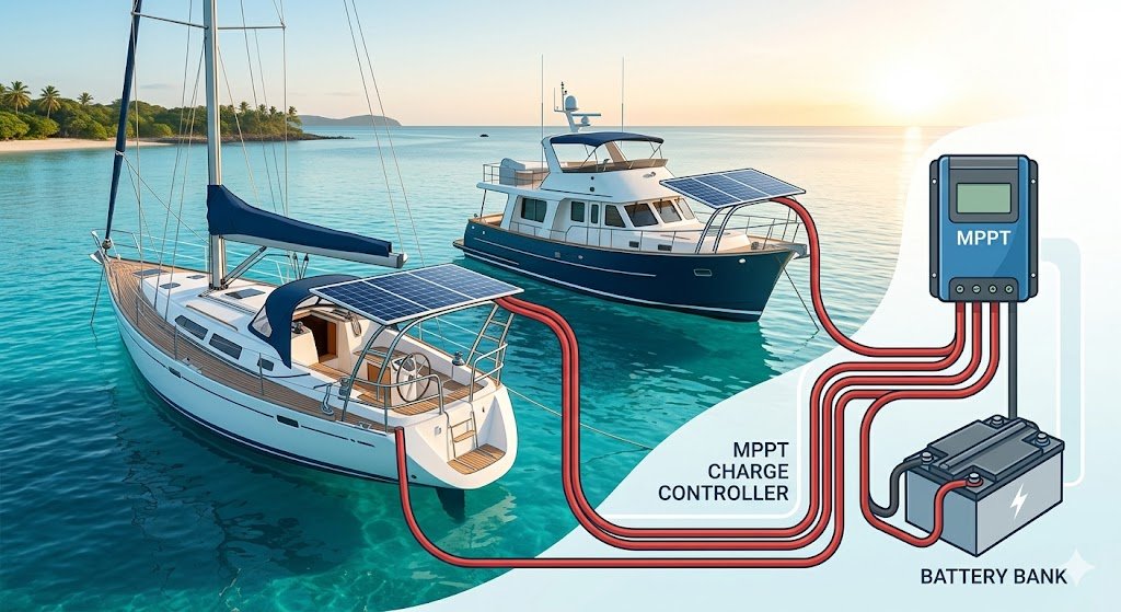
This Marine Solar Charge Controller Size Calculator helps you determine the correct controller amperage for your boat’s solar system based on panel wattage, system voltage, and charging efficiency. It follows ABYC-aligned best practices to ensure your solar charging system is safe, efficient, and properly protected.
Let’s be real: trying to pick the right controller without a plan is a great way to accidentally turn your expensive solar panels into very high-tech, sunbaked ornaments. I’ve seen enough “mystery smoke” coming from under-sized controllers to know that the “cloud-edge effect” isn’t just a myth—it’s a real-world current spike that loves to eat cheap equipment for breakfast. I built this tool so you can stop playing “electrical roulette” and start harvesting every drop of that free Vitamin D from the sun. Let’s get your bank charged up without any unexpected fireworks folks!!
Input Your Data Below
Marine Solar Controller Advisor
Enter system wattage to receive pro-grade wiring advice and safety warnings.
Why does a 600W array require a 63A controller? While the basic math suggests 50A (600W / 12V), the ABYC E-11 standard requires a 1.25 multiplier. This “fudge factor” accounts for the Cloud-Edge Effect, where light reflecting off the side of a cloud can actually cause your panels to output more than their rated wattage for short bursts.
How This Marine Solar Charge Controller Size Calculator Works
Calculates Maximum Solar Current
The Marine Solar Charge Controller Size Calculator determines the peak theoretical amperage your solar array can produce. We use the standard electrical Ohm’s Law formula:
Amps = Watts / Volts
- Amps (I) is the flow of current.
- Watts (P) is the total power of your solar panels.
- Volts (V) is your battery bank voltage (12V, 24V, or 48V).
Pro Insight: For MPPT controllers, this calculation is based on the battery bank voltage, as the controller efficiently converts high-voltage panel input into high-current battery charging.
Applies Safety Margin
Marine systems require a higher standard of safety than land-based systems. Per ABYC E-11 standards, solar charge controllers must be sized to handle 125% of the panel’s rated output.
The Calculation: (Watts / Volts) x 1.25 = Required Controller Amps
The “Why”: Solar panels often exceed their “sticker” rating during the Cloud-Edge Effect (refraction off clouds) or in exceptionally cold, clear conditions. This 25% safety buffer ensures your controller doesn’t overheat or trip breakers during these peak surges.
Intelligent Controller Logic (MPPT vs. PWM)
Not all controllers are created equal, and this Marine Solar Charge Controller Size Calculator understands the technical limitations of each:
- PWM Feedback: If you select PWM for a high-wattage array, the calculator will warn you about efficiency loss. PWM controllers “clip” excess voltage, wasting potential energy that could be charging your batteries.
- Voltage Validation: The tool checks your system voltage and provides specific technical advice to ensure your panel array voltage is high enough to actually initiate a charge.
Built-in Wiring & Safety Advisor
To make this Marine Solar Charge Controller Size Calculator tool foolproof, I have integrated a real-time safety monitor. If your calculated current exceeds 40 Amps, the “Advisor” will automatically trigger a Wiring Alert. This helps to remind you that high-current solar arrays require specialized marine-grade cabling (such as 6 AWG or 4 AWG) to prevent fire hazards and excessive voltage drop. There’s no need to ruin your beautiful boat!
Supports PWM and MPPT Controllers
This calculator is optimized for the two primary types of marine solar regulation:
- MPPT (Maximum Power Point Tracking): The gold standard for boats. These controllers act as a “DC-to-DC converter,” taking high-voltage input from your panels and transforming it into the maximum possible amperage for your battery bank. They are roughly 30% more efficient than PWM.
- PWM (Pulse Width Modulation): A simpler, legacy technology. PWM controllers essentially act as a switch between the panels and the battery. While affordable, they cannot convert excess voltage into current, making them less ideal for modern high-wattage panels.
Step‑by‑Step Instructions
Step 1: Determine Total Solar Wattage
Check the “Sticker” on the back of your solar panels for the Pmax rating. Add the wattage of all panels in your array together (e.g., two 200W panels = 400W total).
Step 2: Select Your Battery System Voltage
Select the nominal voltage of your house battery bank—typically 12V, 24V, or 48V. The Marine Solar Charge Controller Size Calculator uses this to determine the output current the controller must handle.
Step 3: Choose Your Controller Technology
Select MPPT for most modern installs to maximize harvest, or PWM for smaller, budget-friendly maintenance systems. The advisor will provide specific efficiency warnings based on this choice.
Step 4: Review the Advisor Feedback
Don’t just look at the Amperage result! Read the Advisor Feedback box for critical ABYC compliance notes and wiring alerts to ensure your installation is safe and fire-protected.
Example Calculation: The 400W 12V System
To understand why the “Math” matters, consider a standard 400W array on a 12V boat:
- Theoretical Math: 400W / 12V = 33.3 Amps
- ABYC Sizing (125%): 33.3A x 1.25 = 41.6 Amps
- The Result: You should install at least a 42A or 50A controller.
Why the extra 9 Amps? This buffer prevents the controller from burning out during the “Cloud-Edge Effect,” when sunlight reflects off clouds and temporarily spikes your panel output beyond its rated 400W.
ABYC Standards & Best Practices
Proper Overcurrent Protection (Fusing)
While this Marine Solar Charge Controller Size Calculator determines the size of the controller, the ABYC standards require that you protect the wiring that connects it.
- Panel to Controller: You must install a fuse or circuit breaker between the solar array and the charge controller. This protection should be rated at 125% of the panel’s short-circuit current (Isc)
- Controller to Battery: A second fuse is required as close to the battery bank as possible. This fuse protects the wire from the massive energy stored in your batteries in the event of a short circuit.
Wire Sizing for Solar Runs
Even the best MPPT controller cannot overcome the laws of physics. If your wire is too small, you will lose charging voltage to heat.
- The 3% Rule: For critical charging circuits, ABYC recommends no more than a 3% voltage drop.
- Pro Tip: If your solar panels are mounted on a davit or arch far from the batteries, you may need to “up-size” your wire gauge significantly to ensure the voltage reaching the batteries is high enough to complete a full charge cycle. Use our Marine Wire Gauge Calculator to verify your run.
Controller Placement & Environment
Charge controllers are power electronics that generate heat during the conversion process.
- Ventilation: Mount the controller vertically on a non-flammable surface with at least 6 inches of clear space around the cooling fins.
- Proximity: While the controller should be relatively close to the batteries to minimize voltage drop, it must not be mounted directly above lead-acid batteries where corrosive gasses can damage the electronics.
Frequently Asked Questions (FAQ)
What size charge controller do I need?
It depends on your total solar wattage and your battery bank voltage. You must calculate the maximum possible current (Watts / Volts) and then add a 25% safety margin to comply with ABYC standards. Our Marine Solar Charge Controller Size Calculator above automates this math to ensure you select a controller that won’t overheat during peak output.
Do I need MPPT or PWM?
For almost all marine applications, MPPT is recommended. Boats frequently deal with partial shading from masts and rigging; MPPT controllers can track the “Maximum Power Point” to harvest up to 30% more energy than a PWM controller. PWM is only recommended for very small “trickle charge” systems where efficiency isn’t a priority.
Can I oversize a charge controller?
Yes—oversizing is both safe and beneficial. Installing a 60A controller on a system that only requires 40A is perfectly fine; the controller will only pull as much current as the panels provide. This “headroom” allows the controller to run cooler and gives you the ability to add more panels to your array in the future without replacing the controller.
Does this work with lithium (LiFePO4) batteries?
Yes. However, ensure your chosen charge controller has a specific Lithium profile. Lithium batteries have a very flat discharge curve and require precise high-voltage cutoff points. Using an older PWM controller with a “Lead Acid only” profile can damage a Lithium bank.
Safety Notes & Installation Requirements
- Use Marine-Grade Components: Only use UL 1426 tinned copper wire and ignition-protected components. Marine environments will quickly corrode standard automotive or residential equipment.
- Install Proper Fusing: You must have overcurrent protection on both the input side (panels to controller) and the output side (controller to battery). Use our Marine Fuse Size Calculator or our Circuit Breaker Size Calculator to ensure your protection is matched to your wire gauge and peak solar output.
- Follow ABYC E-11 Guidelines: Ensure all connections are secure, torqued to spec, and that no more than four terminals are connected to any one stud.
- Passive Cooling: Most controllers rely on heat sinks. Ensure the unit is mounted in a location with natural airflow; never “bury” a controller inside a sealed, unventilated locker.
Related Tools
Chart a New Course
Ready to size your fuses, breakers, and wires? Return to the main tool station.
⚓ Back to All Marine Tools